zaterdag 26 oktober 2019

DIY LI-Ion Powerwall


Some time ago I got the opportunity to create a powerwall (or more specifically a 'solar generator') for a local scouting group.
They were donated some solar panels but did not have any means to store this solar power and wield at their desired time (mostly during food prep and during night time).
So I started collecting old laptop batteries and e-bike batteries.  
Begun the arduous process of dismanteling these, testing them and sorting them.
I eventually ended up creating a 7s22p battery.

Bill Off Material:
154 18650 batteries
Power inverter
Solar charger
MT50
AC Socket
DC socket (12V and 5V)

Reason for the metal enclosure
The true nature of the this powerwall is rather to be a solar generator to be taken along during a scouting camp.  So I still needed to keep it somewhat mobile but safe to use and most importantly protect the users in case something does go wrong with this DIY setup.


vrijdag 8 december 2017

My IOT garage - the components

One of the gripes I have with my garage is that I have no way of checking whether the garage doors are closed or not.

Why would this be an issue?  Well it happened before that one of the remotes get accidentally hit and one of my garage doors opens up without me knowing it.  As I do not have a line of sight onto the garage doors from my house, I have no way of checking without actually walking up to my garage and seeing if it is closed or not.

Also, garage doors are not really known for their security, if somebody forces up one of the garage doors, I will not know until it is too late.

A second issue with the garage doors is that I only can open them with my remotes.  The keypad I used to have was broken and I took it away, as just pushing the up arrow opened up my garage doors 😨

So what components am I planning to use:
A raspberry pi in a case that can be mounted on a DIN rail.


A waterproof keypad with RFID reader


2 reed switches to detect if my garage doors are open (female connectors already soldered on)


Why the DIN rail housing?
Well there is a fuse box in my garage that has DIN rails where I could mount the raspberry pi to keep dust and insects out.  I might mount it closer to the garage doors in testing phase. But eventually it should end up there.

As the leads from the keypad are quit short, a UTP cable was sacrificed to lengthen most leads coming from the keypad.

Next to the above components there are 2 additional items to add.  An power transformer for the keypad and one for the raspberry pi.


The leads on the reed switches are too short to be installed comfortably.  So a second UTP cable was sacrificed for the greater good.  Its plugs were cut off and on one end they were soldered to the reed switches.


On the other end some connectors were soldered on to connect to the raspberry pi.


However, above setup failed miserably.

The location where this DIN rail housing was located, is not able to connect over WiFi to my house WiFi network.  Most probably due to some brick walls, the distance and the fact that my garage and the small workshop between the garage and my home have metal roofs.
And I tried a lot of options and tweaks.

  • The power adapter for the Raspberry pi, did not seem to be able to provide enough power for the RPi (and the wifi dongle)
  • An ad hoc setup with another RPi, a beefy power supply and an 12dbi antenna still was not able to connect to my WiFi network.
  • I then setup a dedicated RPi access point, also with a 12 dbi antenna, but this did not help either.
  • So, I moved the second RPi in my workshop (the one adjoining my garage) to the closest point to my house.  Then I got some wifi signal from my dedicated RPi access point, but pretty intermittent.
  • Then finally, after using a wifi analyzer, decided to switch back to my regular access point, and voila, connection....

Well most of the time, from time to time connection still drops away, but thats more like every few weeks rather than hours.

So how was I able to move the RPi with the limited leads on the reed switches?

  • I combined 2 RJ45 breakout boards, 2 RJ45 8 pin connectors, 25 meters of UTP cable.
  • On one side I soldered the leads of the read switches to the RJ45 breakout board
  • On the other side I resoldered the connecters for my RPi GPIO pins to the other RJ45 breakout board.

I now have some very basic python code that reads out the GPIO pins and transfers the status of the reed switches to a basic python web service at my house.
The basic python web service receives the messages from my garage, and depending on the status of the reed switches will make one or two LEDs blink to indicate an open garage door.

The end of the struggle, ...no.

  • Occasionally the connection still drops.  The I need to reboot the RPi in my workshop. But I also need to disconnect the wifi adapter before doing so.  That's because the WiFi dongle does not get activated when rebooting. Only when you plug it in afterwards, it works.
  • The python code seems to fail from time to time without an apparent reason.  Although very basic and naive code wise, I would expect it to just keep working.
  • When either the connection or the python code fails, it is not immediately apparent.
  • The keyboard works, but is beeping error sequence. Although everything worked with a dedicated power supply when testing it out, when mounting it on my garage it continuously flashes error.  Especially if I turn on my TL lights :-S


Future plans

  • Some monitoring to see when either the connection dropped or the python code stopped working.
  • Improve Python code to aggregate the readouts when status does not change and send the aggregated readouts occasionally instead of a call each second.
  • Some alerting solution to sms/IM me whenever the status of one of the garage doors changes as I am not constantly looking at the LED equipped RPi.


maandag 29 augustus 2016

Case for Meade ETX125 EC

I recently purchased a second hand Meade ETX125.  Unfortunately it came without a case to safely store and transport it in.

I went on a search for an appropriate case and ended up buying a mobile tool box from Keter in a local DIY store.

It jus barely fits my telescope.  But as it is lacking some padding I purchased some hard insulation, pipe insulation and sound insulation.  After going to work with some scissors, box cutters and spay glue I ended up with an already pretty decent housing for my freshly bought telescope.

Empty tool box with tool insert removed

After gluing on some padding on the sides and adding the insulation


The end result with some sound insulation for further padding and a more 'classy' look
I might give this a spin and see if I can later on add some small storage for the GoTo controller, manuals, eye pieces, ...

zaterdag 31 oktober 2015

Scrap wood table

Some time ago I got inspired by this scrap table to make my own version.

I started out by collecting scrap wood from several sources. The table contains wood from an old bed, a coffee table, pallets, rubberwood countertop, ...

I ripped all these to  similar widths, while trying to maximize the number of strips I could get out of one piece of wood.  Each time I had a batch of these strips I marked the positions where the threaded rods needed to be and made the necessary oval openings with a router.


Initially I just drilled these holes, but due the temporary nature of my work setup and the time between working on this project the measurements were not consistent enough.  And having only a 10mm drill bit for 10 mm diameter threaded rods did not leave much room for error.  This became clear after an initial test fitting which almost did not come apart again.


Putting the table top together took a lot of work and repetition.


  • Fit,
  • Glue,
  • Clamp,
  • Repeat
  • ...


Once the table top was assembled, I straightened out the ends with a circular hand saw.


Due to some 'not-so-precise' measurements, I also had to plug some holes in the table top with some spare wood.


Once glued in place I used a chisel to level it roughly and sanded it down further with the manual plane.

I first planned on just sanding the table top flat, but that just generated too much fine dust.  Therefore I switched to a manual plane.  That sure is a workout :-)


The final planing was done with an electric belt sander with very fine grain sand paper.

Eventually I would like to make an extendable table out of this.  This directed the distances between the threaded rods.  But as I need the table sooner than I could make this an extendable table, I made some temporary support structure.


Although, making this into an extendable table will be a future project.  For now, I will enjoy the table as it is.

maandag 29 juni 2015

Raspberry Pi astrophotography

note: this article is a work in progress, stay tuned for updates

I recently bought a very basic telescope (Celestron Travel Scope 70), not exactly a high end telescope, but I'm still able to get some nice views on planets like Saturn, Jupiter and its moons, Venus and off course the moon.

Being enthusiastic about what I could see with this telescope I have tried taking photographs by manually putting my cell phone camera against the eye piece and minimize my trembling while pushing the button to take picture.

Not surprising that image quality is far from good.  For pics of the moon, it sometimes works out ok.

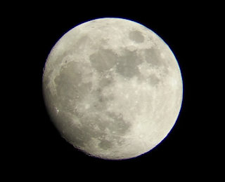
cropped image of the moon taken with my cell phone camera held against my telescopes eye piece


But while the features of Saturn are just distinguishable with the naked eye, it's almost impossible to take a nice picture with the methods described above.

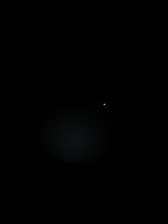
image of Saturn taken with my cell phone camera held against my telescopes eye piece


Also Jupiter and its moons are hard to catch.

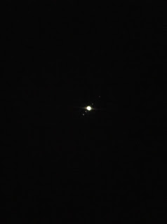
image of Jupiter and moons taken with my cell phone camera held against my telescopes eye piece


Taking it up a notch


Due to this less than ideal situation I decided to take things up a notch and use a raspberry pi camera. I printed an adapter for the Pi Camera to slide over my eye piece using my 3D printer.  After some filing and a paint job I have the adapter ready and I secure the Pi Camera into the adapter with some duct tape.

The idea is to eliminate tremor from holding the cell phone against the eye piece and being able to control the camera remotely.  Eventually I would like to be able to take a clear picture of both Saturn and Jupiter (and its moons).

Raspberry Pi setup


  • I started from a regular raspbian install
  • I enabled the camera, allowed ssh, expanded the file system, 
  • disabled the led on the pi camera [Ref]
  • and configure my wireless setup.

Powering the raspberry pi

I use an USB battery to power the Raspberry Pi setup.

Mount Raspberry pi on telescope.

Currently the Raspberry Pi is basically mounted on the telescope with some zip ties.


To be more comfortable I might need to add a longer ribbon cable between the camera and the Raspberry Pi.

Aiming the telescope

While the Raspberry Pi camera is on the telescope it would be hard to aim it very precisely.  Therefore, I setup streaming so I could check the aiming of the telescope with a laptop or cell phone (as long as I am within reach of my WiFi network) by following this guide.

Taking pictures with Raspberry Pi


Once I  somewhat correctly aimed my telescope I could use the regular Raspberry Pi Camera commands to take pictures of the celestial bodies.

Impressions so far

The pictures I took were not so good as the ones taken with the cell phone, but that is probably due to the low resolution used to take the pictures with the Raspberry Pi Camer.

The way the current adapter is made, it is very fidgety to get it well aligned with the projection from the eye piece.  I have the impression I will have to redesign the eye piece adapter even further to make fitting the adapter on the eye piece easier and to put the raspberry pi camera lens even closer to the eye piece.

Luckily both the Raspberry Pi and the laptop used for aiming were both within reach of my WiFi.

The USB battery could provide sufficient power for the 1 hour I have been testing my setup.

Some test results from 29/06/2015:

Moon in 640x480 resolution

Saturn in 640x480 resolution
Test results 30/06/2015:

moon in 2592 x 1944 resolution

saturn in 2592 x 1944 resolution


arcturus in 2592 x 1944 resolution
Although shot in higher resolution, the improvement is not that great.  The Saturn pic at least shows some interesting shadows.  Not sure whether this is due to my setup, or taking pictures in 'automatic' mode (without defining ISO, brightness, contrast, ...), atmosphere (very warm when pictures were taken) or the limits of my telescope (although naked eye observatory is quit good).

Future ideas / improvements


  • I need to improve the resolution (max resolution is 2592 x 1944, would much better than 640 x 480)
  • Definitely need to start experimenting with my camera settings to get better images
  • automated following / finding, although my Raspberry Pi setup is streaming so I can aim the telescope somewhat while looking at my laptop screen, it would be cool to punch in a celestial body to find and/or follow
  • touchscreen control on Raspberry Pi
  • Have the raspberry pi act as its own APD (or the laptop that is controlling the Raspberry Pi camera) for when I'm not within my home's WiFi range.


References


http://www.raspberrypi-spy.co.uk/2013/05/how-to-disable-the-red-led-on-the-pi-camera-module/
http://pi.gbaman.info/?p=150
https://www.raspberrypi.org/documentation/usage/camera/python/README.md
https://www.raspberrypi.org/documentation/usage/camera/raspicam/README.md
https://www.raspberrypi.org/documentation/usage/camera/raspicam/raspistill.md
https://www.raspberrypi.org/documentation/usage/camera/raspicam/timelapse.md
https://www.raspberrypi.org/documentation/usage/camera/raspicam/raspivid.md
http://zeusbox.net/blog/
http://blog.miguelgrinberg.com/post/how-to-build-and-run-mjpg-streamer-on-the-raspberry-pi

donderdag 9 april 2015

Solving pauzes in 3D print when using OctoPrint

After I installed OctoPrint on my Raspberry Pi 2 model B running Raspbian, my prints regularly paused, resulting in bad prints with lots of blobs.


When googling around for this, a lot of solutions came down to replacing a defective USB cable with a new one.  However, in my case I was sure that the issue was not caused by a bad USB cable as printing directly from laptop using the same USB cable went fine.

The solution to this problem simply came down to adding the following line to the /boot/config.txt file of my Raspbian install:

max_usb_current=1

Please also read the following article providing some more information.

zondag 30 november 2014

From drift wood to tea light holder in 10 minutes flat

This summer, on the beach, I found a nice piece of drift wood that I brought home with me.


I let it dry for a few months and yesterday I transformed it in a tea light holder in just a few minutes.

I started out be positioning some tea lights on the wood to see what would look nice. I marked the location of the tea lights on the log and took it outside.


Once outside, I mounted a hole saw on my hand drill and carefully started to drill out the marked locations. I made sure I was not drilling whole the way through.  After this, I cleaned up the holes with a small chissel.


So after 10 minutes of work I had a nice present for my wife. :-)